Basic information
Technology
To ensure the correct production process and determine all parameters, proper technology and documentation is necessary. In the phase of project implementation for assembly, to ensure full compliance, we consult directly with designers to prepare detailed technological documentation.
Production
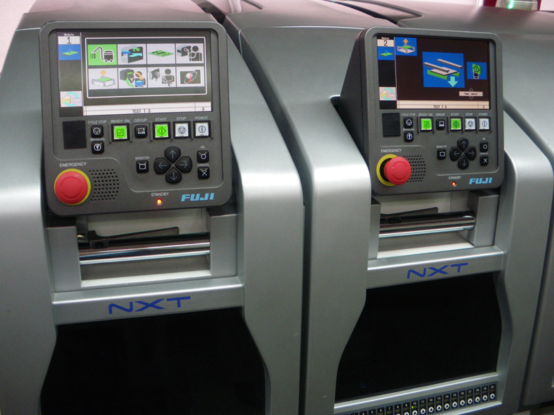
For us, production is a process that faithfully reflects the vision of the designer using modern technologies and the work of specialist staff. The assembly of electronic systems is based on the Fuji NXT automatic line and the ERSA THT threaded assembly line in a nitrogen blanket and 30 manual and mechanical assembly stations.
Quality control
The quality of the final product depends above all everything from the proper preparation of the production process and strict quality control during production. Product assembly and quality control is carried out in accordance with the IPC-A-610D standard. Using modern technology and qualified staff, we guarantee high quality of the offered product and timely execution of orders.
Tests
On clients' request we design and make testers to check given parameters and correct operation of electronic systems.
Examples of basic tests performed in the production process:
- electrical testing of printed circuits and assembled components;
- functional tests.
Protective coatings
The production process is completed with a protective varnish or resin coating. We offer a wide range of available coatings and techniques for their application.
Packaging, printing
As part of the printing services, we offer stickers, instructions, advertising materials, packaging. We carry out packaging designs in accordance with customer recommendations and we implement them. Each product is carefully protected and packaged according to customer requirements.
Logistics and warehouse
Using our many years of experience in material supply chain management, we offer a comprehensive supply service. Bearing in mind the valuable time of our customers, we will take care of the highest quality components, timely delivery and attractive prices. All electronic components used in the process are stored in rooms with appropriate climatic conditions, constantly monitored, ensuring ESD protection. We have a modern, fully automated, warehouse carousel system with electronic identification and readers at every stage of production.
Service
Based on extensive experience of the assembly team, we offer service in the field of electronic disassembly and reassembly surface and threaded elements together with BGA systems and regeneration, repair of electrical and mechanical components and housings.
SMT line

Regionalny Program Operacyjny Województwa Śląskiego - realna odpowiedź na realne potrzeby
Tytuł projektu: "Zwiększenie efektywności, wydajności i bezpieczeństwa produkcji w Firmie Zamel poprzez zakup nowego ciągu maszyn umożliwiającego pracę w technologii bezołowiowej".
Nazwa Beneficjenta: Zakład Mechaniki i Elektroniki ZAMEL Sp. j. Józef Dzida, Katarzyna Łodzińska, Wojciech Dzida|
Wartość projektu: 1 533 935,71 pln
Wartość dofinansowania: 550 222,74 pln
Projekt współfinansowany przez Unię Europejską z Europejskiego Funduszu Rozwoju Regionalnego w ramach Regionalnego Programu Operacyjnego Województwa Śląskiego na lata 2007 - 2013.
Informacje źródłowe na temat Regionalnego Programu Operacyjnego Województwa Śląskiego na lata 2007-2013 znajdują się na stronie internetowej www.rpo-silesia-region.pl

SMT (Surface Mount Technology) assembly line:
- screen printer EKRA X4 PROF;
- FUJI NXT machines, 4 modules. TRAX system (max capacity 37500 el / h according to IPC);
- ELECTROVERT reflow soldering furnace 10 zones (under nitrogen atmosphere);
- ASYS transport line;
- Quality control stations with inspection and measuring microscope (0.01 mm).
Machine park of the SMT line:

The screen printer is adapted to work in-line. It has two independent heads pneumatic, X-axis frame holders with template: minimum size frames 300x300 mm; maximum frame size 737x737 mm (29 inches). Professional System visual EVA with two CCD cameras with 21D inspection enables printing of the print for QFN, Fine Pitch, BGA. The minimum print area of 50x80 mm is perfect in the production of test circuits, small series, dedicated. In addition, the machine offers a maximum printing area of 460 x 460 mm, board thickness 0.5 ÷ 6 mm, repeatability ± 15um @ 6 Sigma print. ZelFlex Z4P 584x584 automatic frame for templates laser cut with four-sided pneumatic tensioning..
- 2 M3 modules with H12S heads with a total capacity of 29,000 cph; range of components 01005 - 5x5 mm; location accuracy of the 3sigma component Cpk> 1.00 +/- 0.050;
- M6 module with H04 head with 5,600 cph output; range of components 0603 - 38x38 mm; location accuracy of the 3sigma component Cpk> 1.00 +/- 0.050;
- M6 module with H01 head with 2,900 cph output; range of components 0603 - 74x74 mm; location accuracy of the 3sigma component Cpk> 1.00 +/- 0.030;
- Fuji Trax software enabling constant control over entrusted components.

- 8 heating zones + two cooling zones with an aggregate;
- soldering in a nitrogen blanket with leveling oxygen content up to 50 ppm in the whole process zone;
- process zone length 3.9 m, width 410 mm;
- lead or unleaded technology;
- maximum temperature 1-6 zone 300C, 7 and 8 zone 350 ° C;
- central adjustable support, regardless of the transport width;
- chain transport;
- unevenness of temperature distribution on the PCB dt < +/- 4 °C.
THT line
THT line equipment:
- element forming station;
- putting elements and hand soldering -20 stations;
- ERSA-ETS330 soldering wave, SAC305 charge (soldering in a nitrogen atmosphere);
- assembly of mechanical components -10 stations;
- inspection and repair station.
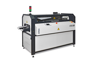 Technical data of the Ersa ETS-330 soldering wave:
- heating zone length 600 ÷ 800 mm;
- fluxing spray;
- transport speed 0.5 ÷ 2.5 m / min, in frames;
- SAC305 charge;
- nitrogen shield;
- Ersa LM 8 soldering module (6.2 kW) / crucible, 330 mm width;
- transport angle adjustment;
- laminar and turbulent wave.
- heating zone length 600 ÷ 800 mm;

Technical conditions
General conditions for accepting assembly orders
To ensure timely and correct execution of the order, the relevant documentation and components must be delivered to the contractor (when assembling from entrusted elements). Transfer of incorrect production documentation, introduction of undocumented additional changes may result in producing a different version of the product than planned. If, after placing the order, some difficulties arise, they may result in a corresponding price increase. Such difficulties include, for example, the need to correct incorrect documentation, incorrectly packaged elements, incompatibility in the elements list with the design or delivery status, which may result in a corresponding price increase. In order to facilitate the ordering party's preparation of relevant documentation and files, we provide some tips and information that should be used at the stage of order preparation:
-
Production parameters - SMT technology:
- the size of the smallest component 0402 (1x0.5 mm);
- size of the largest component 55x55 mm;
- minimum component height 0.3 mm;
- maximum component height 13.5 mm;
- weight up to 25 grams;
- pressure force programmed from 1 to 10 N;
- PCB thickness 0.5 ÷ 6 mm;
- PCB size from 50x80 mm to 460x460 mm;
Requirements for the documentation sent by the Principal
- Gerber 274X sets for the TOP, BOTTOM, TOP_PASTE_MASK layers, BOTTOM_PASTE_MASK (paste templates), TOP_GLUE_MASK, BOTTOM_GLUE_MASK (adhesive templates), mechanical layers with tile and panel contours. Alternatively a complete PCB file.
- Pick & Place file (Windows formatting, ANSI utf8 encoding without boom) from coordinates of the center of the components (description below), or .xls format (97-2004) in the form of a table. The Pick & Place file has a text format. Each line contains the parameters of a single element. The parameter separator is a space character. The item description should include:
- element designator, e.g. R1;
- value or name e.g. 1K-1%, MSP 430F135;
- housing, e.g. 1206, PQFP64;
- coordinates of the element's center in millimeters x y e.g. 1.234 5.678;
- component rotation angle in degrees e.g. 90.0;
- T-top, B-Bottom assembly layer.
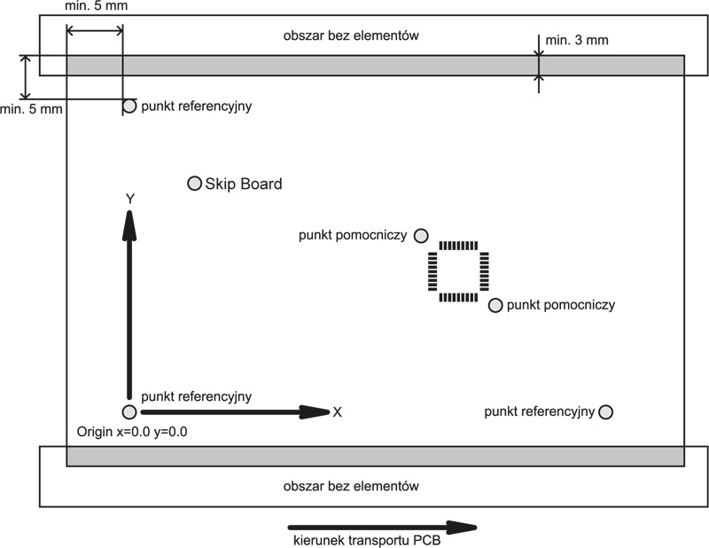
Please place zero origin coordinates at the location of one of the reference points.
Example of pick & place file - text format:
name value housing x y angle layer R1 1K-1% 0603 10.120 8.200 90.0 T R2 2K2-1% 0603 1.234 5.678 180.0 B Sample data of the pick & place file placed in one table - xls format.
Element coordinates:Name Item value Housing X [mm] Y [mm] Angle of rotation Page R1 1kΩ1% 0603 10.120 8,200 90.0 T R2 2,2kΩ1% 0603 1.234 5.678 180.0 B Coordinates of base points (Fiducials) - Fid.1 (x, y)
Name of the base point X [mm] Y [mm] Fid.1 -15.05 13.02 Fid.2 30.05 20.02 InkSpot coordinates - Ink.1 (x, y)
InkSpot point name X [mm] Y [mm] Ink.1 -11.05 14.02 Ink.2 20.05 12.02
A two-dimensional Cartesian coordinate system with a left-hand rotation axis should be used.Other systems may be used provided a description is provided.The catalog with files should be zipped and sent with the name of the project, plate, version.We can also do these activities ourselves after sending the complete PCB project. - List of elements -BOM (Bill Of Material) for one block in Excel format.The documentation should contain the following information:
- element data (manufacturer, housing, designators, value, tolerance, SMT / THT, top / bottom);
- element packaging (tape, tray, stick). All components must be in original ESD packaging adapted for SMT;
- origin of materials (own purchase or entrusted material);
- producer code;
- are these items made in a special version;
- indicating which elements require restraint or special assembly;
- PDF files with documentation of components with unusual housings or soldering profiles.
- Diagram - assembly drawing of arrangement of elements on PCB (PDF, PCB, Gerber 274Xwith description layers, provided they contain item designators).The polarities of the elements in the drawings must be clearly marked. In the case of unusual markings, please document in PDF.
- Descriptive file (txt) with defined block and whole panel sizes.Provide the block raster and coordinates of the first block and the drawing of the entire panel.
Design requirements
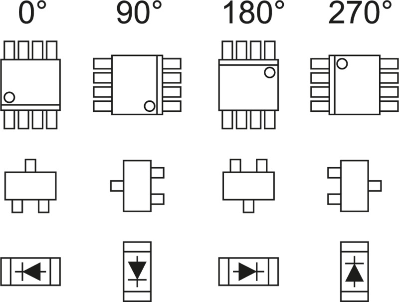
- Angle of rotation of the elements in degrees and polarization of the elements.
 SMD components will be mounted on plates adapted for automatic assembly. To ensure faultless assembly, pay attention to the correct marking of the polarity of the elements both in the design and the assembly documentation provided.
Designation it should be unambiguous and legible. Examples of markings for our machines: - Fiducials reference points
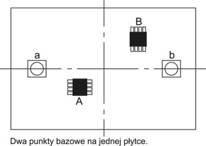 For positioning the panel a minimum of two reference points on the PCB are required in the machine. The points should have a regular shape: square, circle, cross with a distance of at least 1mm from the solder mask. The surface must be smooth and reflect light well. The spots must not be on the layers of paste mask.
 For proper centering, two points diagonally on the PCB are enough, but for greater precision we recommend placing three fiducials - the PCB deformation is corrected. We place the points as far as possible from each other. For QFP, BGA circuits use auxiliary points located on the diagonals of the integrated circuits.
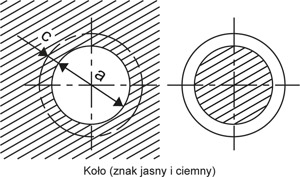 If the PCB has a large surface area and contains circuits with a small grid, it may be that the arrangement pads along the entire axis is not linear. Auxiliary points increase the precision of positioning of individual systems. Recommended dimensions of reference points:
- permissible dimensions for a square 1.2 ÷ 2.2 mm. Recommended 1.8 mm;
- permissible wheel diameters a = 1.2 ÷ 2.2 mm. c = 0.3 mm;
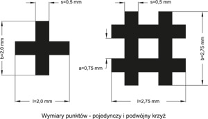
- allowable dimensions for single and double cross shapes.
- Transport of plates between machines
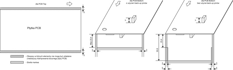
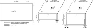 The plates are transported on edge conveyor belts that overlap 3 mm on the PCB on each side on the bottom layer. There must be no items in these areas. For double-sided SMD boards, this applies to both sides of the PCB. PCB panels in one series must have identical external dimensions (tolerance +/- 0.6mm).
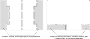 The panel shape should be rectangular - fillings should be used for irregular block shapes. Transport edges must be parallel to each other.
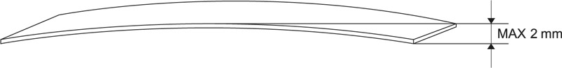
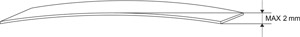 The maximum plate bend can be 1mm. Store tile packages on flat surfaces
 - Skip damaged tiles on the panel (InkSpot)
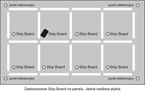 The InkSpot point allows painting (e.g. with a felt-tip pen) and rejecting faulty PCBs placed on one panel. InkSpot's shape and dimensions are similar to fiducial.
 - Panelization
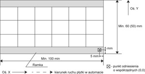 For PCB paneling, two variants of block placement in the technological frame or without (then reference points on each PCB in the panel). For wider panels, it is necessary to leave a free space of 5mm in the middle of the panel for the central support mechanism in the furnace.
At your request, we can suggest a paneling method.
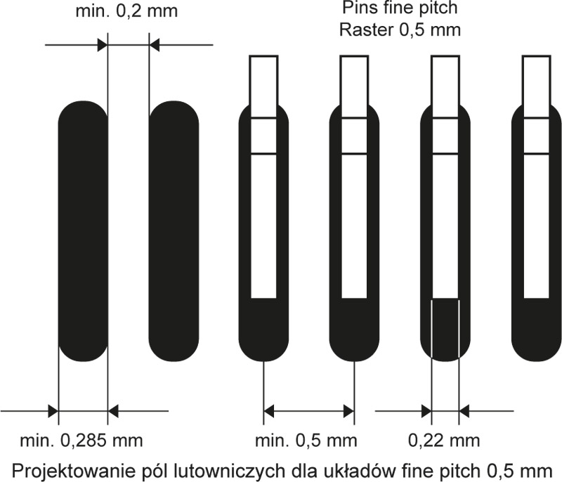
- Designing soldering pads
Fields for components should be designed according to the manufacturer's documentation (SMT, THT). In general, the following rules should be followed: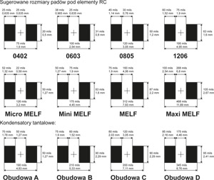
- pad size cannot be smaller than the tip size + 30µm on each side,

- the gap between pads must not be less than 200µm (systems fine pitch 0.5mm);
- distances between elements should not be less than 1mm;
- take into account the difference in pads for reflow and wave soldering technology;
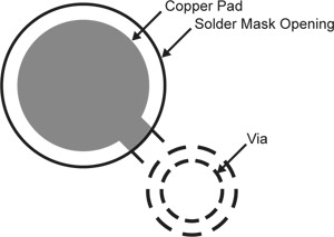
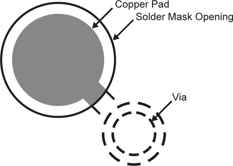
- solder pads for BGA systems - according to the system manufacturer's documentation, which contains the required pad diameters, vias and connection paths.
- gap between pad and solder mask should not be less than 80µm.
- Thermal capacity pad-track-via
Avoid using and guides and thick paths connected directly to soldering pads. Such elements significantly increase the thermal capacity of the pad. There is a risk of a tombstone effect for components due to uneven surface tension of the melted paste.
- Preparation of the template for applying the paste
Proper preparation of the template design requires experience and professional knowledge. The template should cut out perforation adapted to the specific type of frame and printer. Template design is done on our own.
- Completion of elements
We recommend assembly with elements entrusted and purchased by our company. We offer most of the typical RC components that we sell at wholesale prices. On request, we provide full assembly of elements. Most components are imported directly from manufacturers.
- Elements supplied by the customer
Elements should be sent in original ESD packaging. An appropriate number of items should be provided with reserves:- elements delivered in tapes including a 3% surplus compared to the amount specified in the documentation, but not less than 10 items. With breakouts at least 5 cm of tape without elements + 20 cm foil. If there is no runaway, we stick the section, but the elements from the first 5 cm of tape are lost;
- elements supplied in the strips:
- for SO enclosures, with a 3% excess in relation to the amount specified in the documentation - but not less than 5 pcs
- for TSSOP enclosures, with a 5% excess in relation to the amount specified in the documentation - but not less than 10 pcs.
- for others, including a 5% surplus over the amount specified in the documentation - but not less than 5 items;
- items supplied in trays - including 0.5% surplus in relation to the amount specified in the documentation - but not less than 1 item (in the case of a high price value of an individual arrangement);
- threaded elements - including a 1% surplus over the amount specified in the documentation - but not less than 5 items;
- connectors or mechanical components e 3% of the surplus in relation to the amount specified in the documentation, but not less than 10 items;
- specific and dedicated components individual arrangements, but not less than 1 pc . surplus element.
- Quality IPC-A-610D
Installation is carried out based on the IPC-A-610D standard . All employees related to assembly have been trained and have valid certificates. For commercial devices we provide class II, for medical and military class III. When ordering, please select the class and comments regarding the custom assembly.


Data for valuation
In order to evaluate the cost of assembly, please provide:
- PCB and project data:
- Files (Gerber, Protel, Eagle or another graphic file with a view of the elements).
- Dimensions, thickness and material of the board, way of dividing blocks, milling.
- Number of layers, thickness of copper and other coatings - if there are special requirements.
- Cover for Sn-Pb, Pb-free, HAL, Au or other soldering pads. We use SAC305 for the wave.
- Execution in the form of a single board and board (how many boards in one board, board dimensions, board drawing).
- Metalized or non-metallized holes.
- Do the PCB have special markings, stickers.
- View of the board with mounted elements and designators -top / bottom.
- The customer will provide files for the template for applying paste and glue, and Pick & Place files to write the program.
- List of elements -BOM for one block (Excel or text format)
SMD components will be mounted on plates adapted for automatic assembly (the plate must contain reference points - fiducials). Basic information:- Element data (manufacturer, housing, designators, value, tolerance, SMT / THT, top / bottom).
- Packaging of the elements (tape, tray, stick). Necessary condition - all items must be in their original packaging.
- Origin of materials (own purchase or entrusted material).
- Manufacturer's code for items supplied by us.
- Are these items made in a special way?
- Which elements require restraint or special assembly.
- For small series, the Customer will provide custom elements.
- Production volume, production series - production schedule, delivery.
We can customize shipments to cyclical dates or an individual schedule provided by the Customer.
- Packing method:
- Bulk packaging, boxes, ESD bags, labels.
- Delivery method, shipping frequency.
- Testing method, test time, who supplies / performs the tester.
Assembly control 100% visual, in addition the possibility of making special tests, testers on request.
- Mechanical assembly (e.g. enclosures, screens, heat sinks):
- Documentation for the mechanical part (BOM, drawings, photos).
- Description of the assembly method (tools, photos, drawings).
- In case of necessity to pour resin on the systems or cover them. varnish - type and amount of material, thickness of coatings.
- If you perform additional mechanical activities, please send detailed instructions and a pattern.